Last Reviewed:
January 11, 2026
| These techniques will work on any vehicle, just measure your particular vehicle and change the sizes of each component fabricated. | |
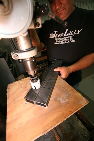 |
1. Mounting a NASCAR Sway bar calls for heavy duty mounting pads so we used 1x2 inch tubing, 1/8th inch thick. First we tacked two pieces together and then we marked them at the correct angle to match the frame. Using a two inch hole saw, we then cut through the center of one tube for a bushing. |
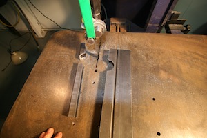 |
2. Next we marked the center line of the hole and sliced the tube in half. |
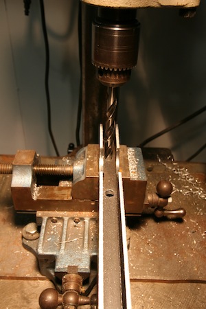 |
3. Here we flipped the tubing over and drilled two 7/16th inch holes through both tubes, 3/16th of an inch outside the bushing saddle hole. The idea is to make them close enough for maximum strength but far enough away for mounting bolt clearance. |
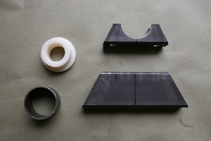 |
4. As this pictures shows, when we cut the two pieces of tubing at the proper angle they separated. The bottom (larger) piece will be the mounting pad, welded to the frame. The center line is for reference to assure all the holes are dead on. |
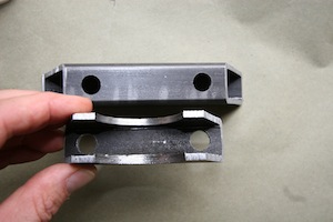 |
5. This view shows how we trimmed the saddle and it's now ready for welding. |
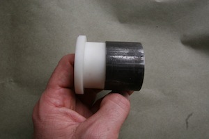 |
6. The bushing will be pressed into the tube sleeve for a tight fit. |
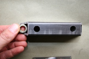 |
7. We had to grind a little of the nuts to make them fit inside the tubing. |
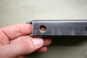 |
8. Once the nuts fit properly we welded them in place to eliminate the need for a wrench. |
|
|
|
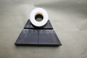 |
9. This is what it will ultimately look like. |
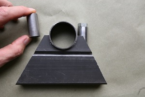 |
10. Here we put the bushing sleeve on the saddle to test the fit. Then we cut some small round tubing to fit the 7/16 grade eight bolts we will use. We placed them next to the sleeve to check the clearance before welding everything together. |
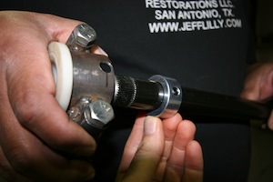 |
11. Here we pressed the nylon bushing into the sleeve and slid the retaining collar over the shaft. This will keep the sway bar from walking left to right in the bushing during hard use and is a necessary safety measure. The hole on the top of the sleeve is to allow tightening of an allen head set screw in the bushing collar. |
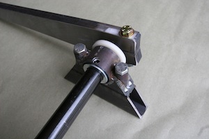 |
12. This close up shows the unit ready to be mounted and tested. |
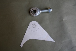 |
13. For the rear sway bar, we made this paper template for making the mounting bracket we will need to attach the sway bar to our 9 inch Ford rear end. |
 |
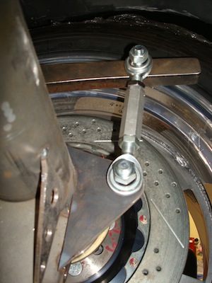
14. Here it is attached as we look to assure there is ample clearance between the sway bar, exhaust and rear wheel. |
 |
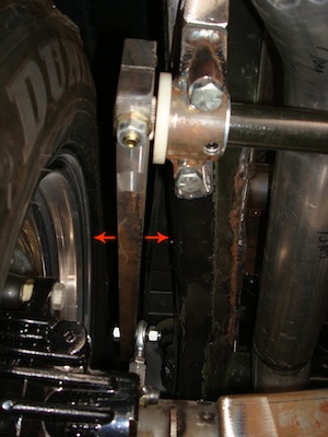
15. And here is a close-up of the mounting bracket. |
 |
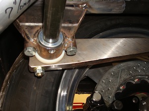
16. This pictures shows that we have good clearance between the tire and frame rail. |
 |
17. And here is another view of our installation. |
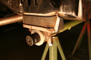 |
18. For the front sway bar we had to make a riser to clear the frame and core support. We brought it down 2.5 inches. The sway bar mount is identical to the ones we made for the rear. |
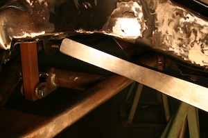 |
19. This picture shows that the sway bar ends had to be bent to avoid hitting the frame. Cold bending is best for this job. |
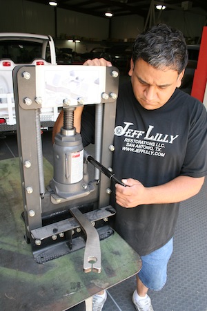 |
20. We marked the spot and used a 25 ton press to make the bend. |
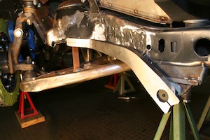 |
21. And now the bar clears the frame with a 3/8ths inch clearance. |
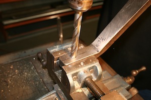 |
22. Here we are drilling the bar for the rod end link. |
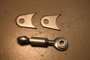 |
23. And here you can see the small tabs we made to hold the link solid to the lower control arm. |
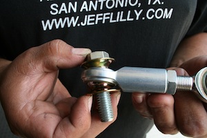 |
24. We used special rod end ball bushings to allow greater movement. |
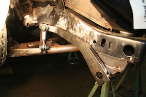 |
25. And here is the front sway bar install and ready to go. |
Jeff Lilly Restorations
11125 F.M.1560 N
San Antonio, Texas
210-695-5151 - www.jefflilly.com
11125 F.M.1560 N
San Antonio, Texas
210-695-5151 - www.jefflilly.com


