Last Reviewed:
January 11, 2026
| This system can be retrofitted for many vehicles providing there is ample room in the roof pillar for the retractor to sit flush. It has not been crash tested but it is built with stronger material than used by manufacturers. | |
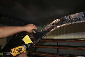 |
1. We start by drilling out the welds to remove the section of the interior roof panel that supports the headliner bows. |
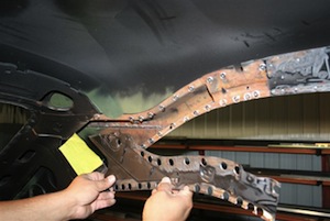 |
2. This is where we will put the retractor assembly for the shoulder belt. |
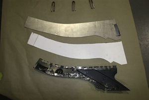 |
3. We used the original roof panel as a template to make a cardboard pattern and then use that to cut out a new metal plate to hold the new retractor. |
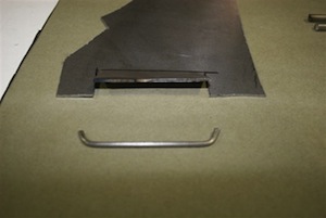 |
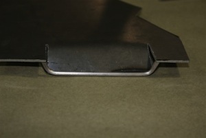
4. On the wide end of the plate, we cut the metal slightly wider than the seatbelt and turned it up so the belt will slide smoothly. Then we formed a piece of 1/4 inch stainless steel wire to fit the opening to assure the belt does not catch or chafe. |
 |
5. And here you can see that we have welded the wire into place. |
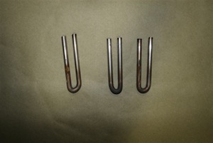 |
6. Then we made three small u-shaped guides out of 1/4 inch stainless rod. We will polish them on the inside to assure smooth action. |
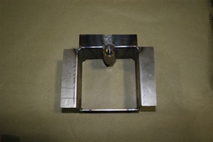 |
7. Here is the seatbelt retractor box we made for the roof pillar. The retractor assembly will be bolted to the long nut. |
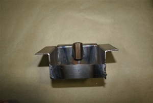 |
8. Here is another view of the seatbelt retractor box. Once everything is ready we will weld this to the roof. |
|
|
|
 |
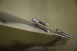
9. And here we have added the u-shaped guides to the new roof panel piece in a slight arch to assure the belt will move easily. |
 |
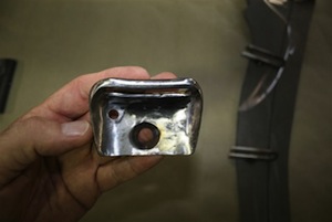
10. Here is another view of the u-shaped guides. |
 |
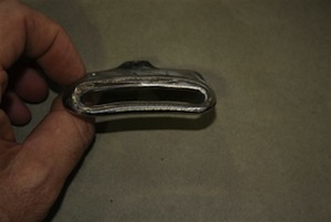
11. We made this seat buckle bezel out of 16 gauge stainless steel. It will eventually be black chromed to blend with the headliner. We will use a flathead bolt to mount it through the large countersunk hole. The small hole is for a locator pin to keep it from turning. |
 |
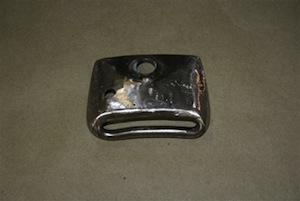
12. This is the end view of the same piece. We used 1/4 inch stainless rod to line the hole and curved the top slightly so it will fit nicely against the headliner. |
 |
13. And here is a top view of the bezel. |
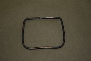 |
14. We made this ring out of 1/8 rod. It will be welded around the outside of the bezel to hold the headliner in place. |
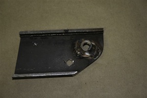 |
15. Here is the support bracket we made for the bezel. It will be welded to the roof pillar. |
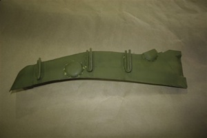 |
16. Here is the new guide plate welded and primed on the back side and ready to install. |
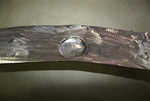 |
17. On the front side of the guide plate you can see that we had to add a recessed cup to hold a headliner bow. You will see why this was necessary when we put it all together. |
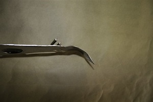 |
18. Here you can see how we bent the guide piece to match the bezel and headliner. |
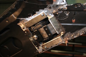 |
19. This is a picture of the retractor box with the belt assembly attached via the long nut we welded on. |
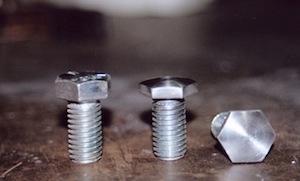 |
20. This picture shows how we had to shave off the top of the retractor bolt to allow for clearance between the retractor box and roof pillar panel. |
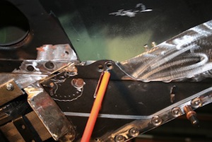 |
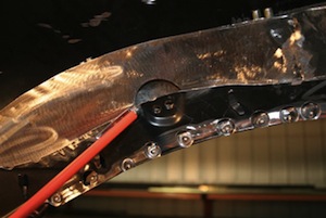
21. We put part of the original roof panel with the headliner holes back in the factory location. |
 |
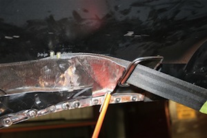
22. And here you can see that the original panel lines up with the recessed section on the guide plate. You can also see why we had to make a cup for the headliner bow. |
 |
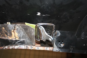
23. The belt moves freely out of the guide. Notice the ring we made for the headliner. |
 |
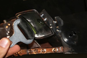
24. Here is a closeup of the bezel plate. Notice that when the belt is retracted only the end piece is exposed. |
 |
25. And here you can see how easy it is to reach up and pull out the seatbelt. |
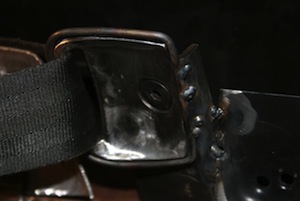 |
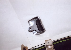
26. This close up shows the 1/8 inch clearance around the bezel. The headliner will be wrapped and glued around the wire ring. |
 |
27. And here is a cardboard mockup to show how the seatbelt will look when we have finished the project. Our headliner will be black and the bezel ring will be black chromed to match. |
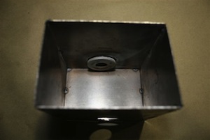 |
28. Now we have to make two floor retractor boxes but fortunately the task will be far easier. We start by making the outside box out of stainless steel plate, which will be set into the floorboard next to the step plate. |
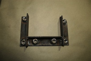 |
29. Then we make a bezel to fit around the hole we will cut in the floorboard. |
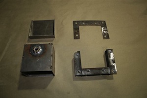 |
30. And here are the four pieces we made, ready to be installed. |
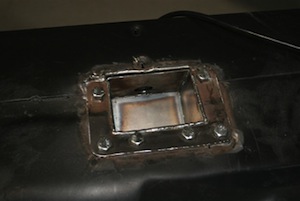 |
31. We used standard bolts to make sure everything fit correctly. We will use countersunk bolts for the final assembly. |
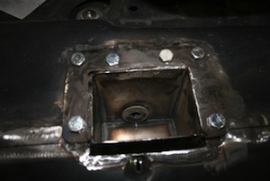 |
32. In this close up you can see that we welded washers in the box for added strength around the retractor bolt. |
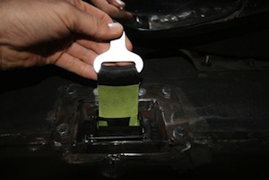 |
33. And here is the assembly with the belt installed. We will make a trim piece to cover up the mechanism and chrome plate it black to match the carpet. |
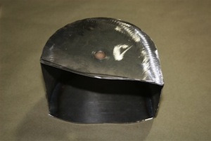 |
34. For the inside retractor, we made a cup that will be welded in the floor next to the center console. |
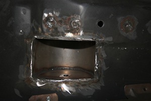 |
35. And here it is in place and ready for the retractor assembly. |
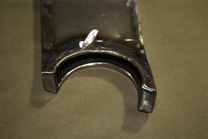 |
36. this belt ends with the retractor belt coupler so here we made a special cradle for the coupler. |
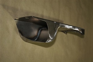 |
37. The bottom view of the cradle shows that we cut out a section to allow the belt to adjust to the diameter of the user. |
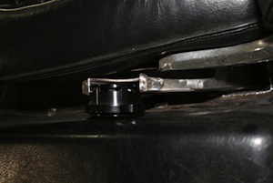 |
38. And here it is in place with the belt and coupler installed. |
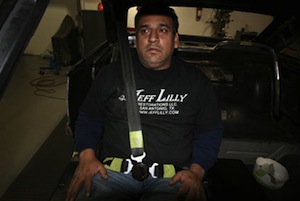 |
39. The final test before sending everything out for plating is to see how it fits a live body. |
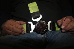 |
40. Simply twist the coupler and the three belts retract simultaneously. |
Jeff Lilly Restorations
11125 F.M.1560 N
San Antonio, Texas
210-695-5151 - www.jefflilly.com
11125 F.M.1560 N
San Antonio, Texas
210-695-5151 - www.jefflilly.com


