Last Reviewed:
January 11, 2026
| This article will show you how to build a custom exhaust system from the headers to the tail pipe. We will use two small mufflers on each side to improve the appearance and flow characteristics and three inch diameter exhaust pipe. | |
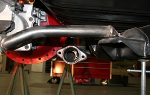 |
1. The first thing to look at is the angle of the header collector flanges. In this case, the passenger side is pointing inward and slightly down, and the driver side is pointing almost straight back and down. We want both to point straight back and parallel to the ground. |
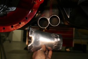 |
2. We cut off the driver side collector flange by slicing the factory weld. Then we carefully ground away the welds. We also cut off the mount flange at the end of the collector so we can add V-band clamps for a perfect seal. |
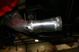 |
3. Here we have reinstalled the driver side flange in the desired position. |
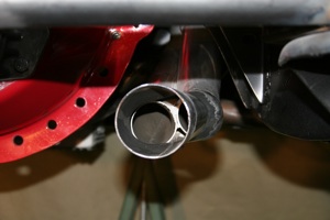 |
4. The passenger side was not too far off so we went at it with a hard rubber hammer. |
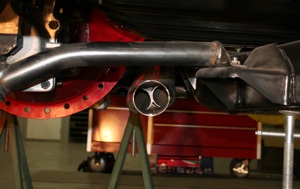 |
5. And here it is facing straight back. |
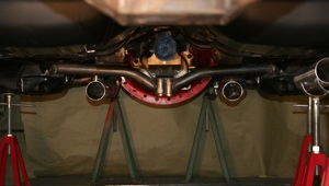 |
6. Now the two sides are straight and parallel and in the same position relative to the transmission cross member. |
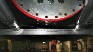 |
7. Looking from the front, we used a straight edge to assure the hight and side to side positions are identical on both sides relative to the frame. |
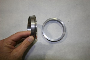 |
8. V-Band clamps are the best solution for a perfect, no leak, seal and allow you to disconnect the pipes if necessary. They consist of two sealing rings that are welded onto the ends of the header flange and exhaust pipe and a clamp. |
|
|
|
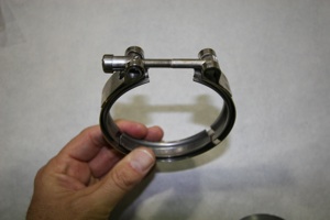 |
9. The stainless steel clamp has a channel that matches the flanges on the two rings, assuring a tight seal. |
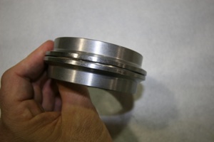 |
10. You should try to get the two rings a parallel as possible before welding them in place. However the clamp will pull small gaps together. |
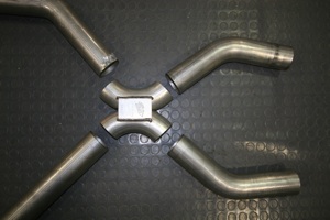 |
11. Our design calls for an ´X´ pipe in the center of the system. We will mark for fit and then trim the pipes to get the gaps just right. We are using standard 90 and 45 degree pieces for this, available at most auto supply stores. |
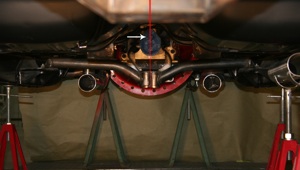 |
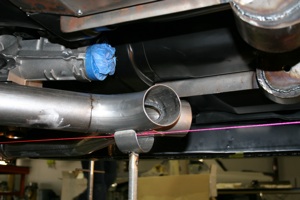
12. We start by running a center line string from front to back to keep us on track while we build the system. |
 |
13. Exhaust pipe stands come in handy because the threaded risers can be easily adjusted for the proper height. |
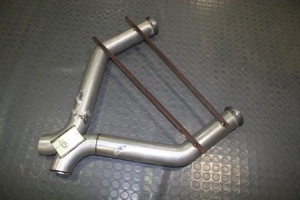 |
14. We marked, cut and tacked the sealing rings to the X-pipe while it was in place under the car. And we also tacked on two pieces of 1/2 angle to stabilize the structure. We will grind the tack welds away when we are done. |
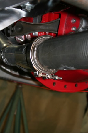 |
15. This is how the V-clamp will look once we are done. However we will rotate the clamp nut to the top side out of sight.. |
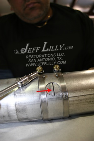 |
16. Here is a trick we use to line up pipes we intend to weld. We took a piece of exhaust pipe and cut it in half, drilled a 3/4 inch hole in each half, and then tacked on two hose clamps. The holes let us see that we have the proper gap for welding and gives us access for two tack welds to hold the pipes in place when the clamp is removed. |
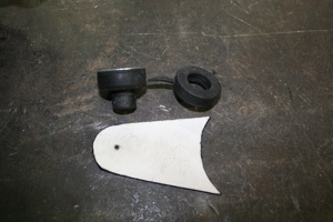 |
17. Here we have made a template for a simple exhaust tubing hanger. The rubber isolater were purchased at a local parts store. |
 |
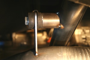
18. As seen here, we cut two sections from the template and installed the rubber grommets on both sides. This design allows the pipe to move up and down with the engine. |
 |
19. Here we welded a short piece of tubing onto a cross member for half of the hanger. The nut is welded inside the tube. |
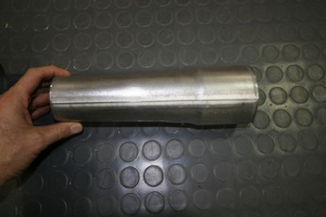 |
20. This special piece of transition tubing goes from round to oval to give us more clearance under the floor pan. |
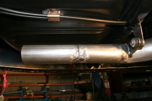 |
21. Here we have welded the transition tubing to the cross flow section, giving us three inches of clearance to the floor, which will reduce the heat felt by the occupants. |
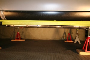 |
22. Here we put yellow tape on the frame to contrast with the exhaust pipe to so we can make sure the two are parallel for the full length. |
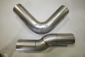 |
23. The front muffler needs to be a little bit higher so we cut this 90 degree piece in four sections and reassembled it to achieve the needed rise. We never put exhaust components closer than two inches to the floor pan to allow adequate cooling.. |
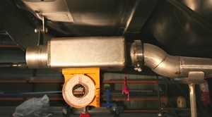 |
24. And here is the front muffler in place. The protractor shows us that it is parallel to the ground. |
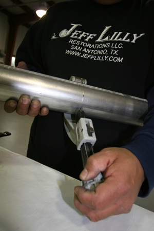 |
25. Another trick we use is to use a tubing cutter to mark the pipe before cutting it on a band saw. This is easier and more accurate than trying to mark it with a felt pen or pencil.. |
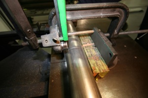 |
26. Here is the pipe mounted in the band saw and you can clearly see the mark. |
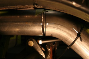 |
27. The two arrows to the left show where we have marked the pipe for grinding to improve the fit. The arrow to the right points to a nylon strap we used to temporarily hold the pipe in place. |
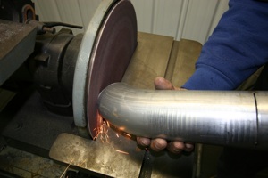 |
28. We use a disc grinder to dress the ends of the tubes. |
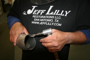 |
29. And we use a carbide burr tool to clean up the inside. |
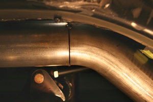 |
30. Back in place, we used the tack weld clamp setup to hold it in place and now it is ready to be welded all the way around. |
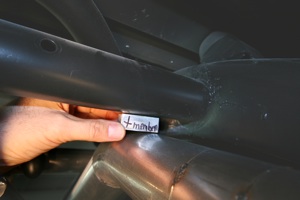 |
31. We keep all exhaust components at least 3/4 of an inch away from the frame, cross members and other parts to assure there are no vibrations. |
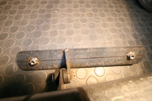 |
32. We made our muffler mounting bracket from 1/8th inch hot rolled steel strap. |
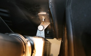 |
33. And here it is installed to the floor above the muffler. |
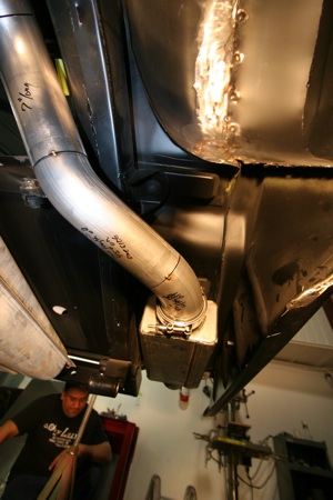 |
34. Here is how we made the exhaust pipe wind from the front muffler, around the fuel tank, toward the rear of the car with standard 90 and 45 degree pieces of pipe. |
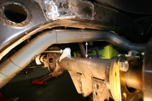 |
35. We provided five inches of clearance between the exhaust pipe and rear axle housing (white arrow) to assure it would not be hit when going over speed bumps. |
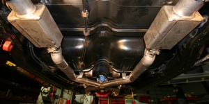 |
36. Both mufflers look identical when viewed from the rear. |
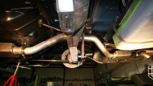 |
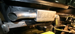
37. Here you can see that each side has two mufflers to quiet the engine with minimal restrictions. |
 |
38. The tail pipe is simply angled down and out to minimize the amount of road dust that is kicked up. The final step is to weld up the pipes and apply a ultra heat coating. www.longlife.co.uk |
Jeff Lilly Restorations
11125 F.M.1560 N
San Antonio, Texas
210-695-5151 - www.jefflilly.com
11125 F.M.1560 N
San Antonio, Texas
210-695-5151 - www.jefflilly.com


