


Last Reviewed:
June 07, 2026
| Steps 1-20 describe how we installed a new fuel pump and lines. And steps 20-36 will show you some of the tools and techniques we use for flaring and routing hydraulic lines for the clutch and brakes. | |
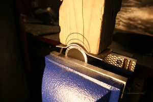 |
1. Our first project is to make saddle brackets to mount a fuel pump. We found a piece of tubing the size of the pump housing and cut out the same size curve in a block of wood. Then we squeezed a piece of 18 gauge metal between the two to form the saddle. |
 |
2. As you can see, it does a nice job. The next step was to bend the outside lips to form the saddle shown below. |
 |
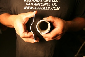
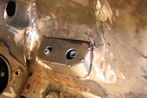
3. We welded the saddles to a piece of 14 gauge metal and rounded the corners. And we attached four studs to the plate for the fuel pump hold down brackets. |
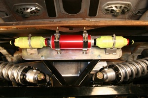 |
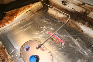
4. In this picture the whole assembly has been mounted on the custom suspension system we built previously which is directly under the fuel tank. |
 |
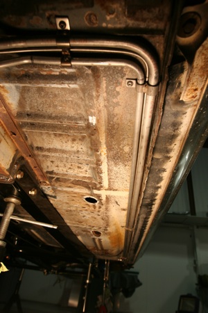
5. Next we cut a section out of the torque box so we could install a U-shade channel up against the floor to make the fuel line flush with the floor. This looks good and will protect the line from being squashed by a floor jack. |
 |
6. We made the U-shaped channel wide enough to hold both the brake and fuel lines. |
|
|
|
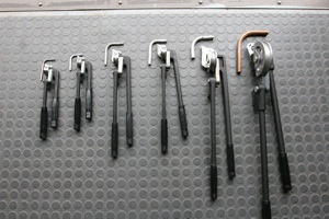 |
7. It pays to have the right tool for the job and that is particularly true when bending tubing. Here is our set of benders, along with sample bends, which we use to make templates. |
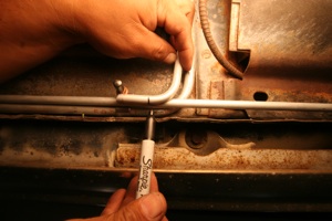 |
8. For example, in this picture the straight tubing needs to be bent to go inside the existing line so we simply held up the appropriate template bend and transferred the mark for the bender. |
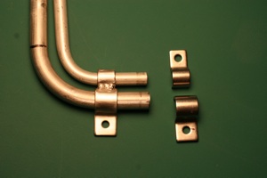 |
9. We could not find double clamps for two different sizes of tubing so we made our own by cutting up two clamps and welding them together. |
 |
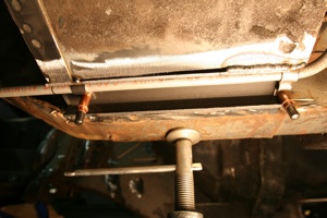
10. It pays to take the time to make the proper clamps and assure that everything is neat and straight, as shown. |
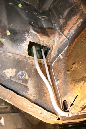 |
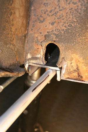
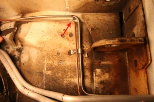
11. Here you can see where the lines come out of the U-shaped channel we made and head up through the fender apron. The fuel vent line goes straight up but we added a couple of minor bends to the supply line to make room for the hoses and fittings. |
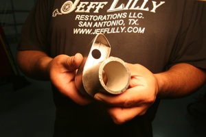 |
12. We wrapped a piece of 18 gauge steel around this piece of tubing to shape the sides of a base plate for the lines to pass through the fender apron. |
 |
13. And then we tacked the base plate on the top side of the fender apron. |
 |
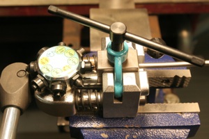
14. Here is another method for figuring out bends. We simply used a piece of brass rod to test the layout and set the proper angle to avoid wasting tubing. |
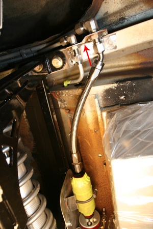 |
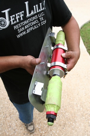
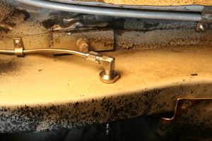
15. Here you can see that we ran the fuel pump output and bent lines through a bracket we made and attached to the frame. Notice that we used a stainless steel flex hose between the frame and pump to allow for minor vibrations.. |
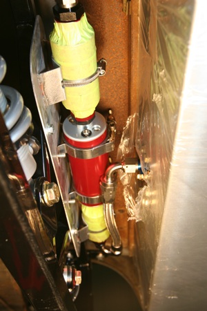 |
16. Here you can see that we also used a flex line on the input side, before connecting it to the fuel tank. |
 |
17. And here is a view of the top of the tank showing the vent line. |
 |
18. We used ´thru frame´ fittings (made by Godmans) to pass the lines through the frame. |
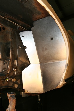 |
19. We made a splash shield to protect the lines from tire dirt under the fenders. |
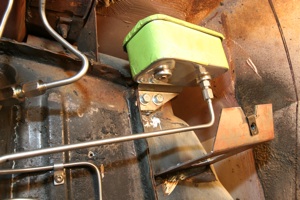 |
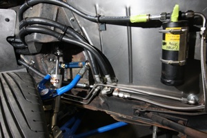
20. Here is a view of the hydraulic clutch reservoir, hidden up under the fender but still accessible for service. |
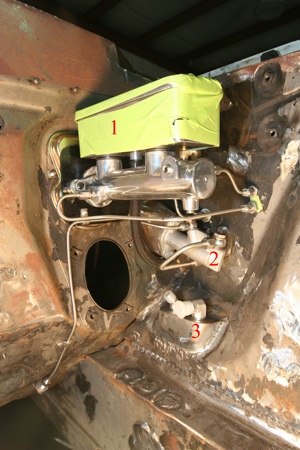 |
21. And here is a view from the engine compartment showing the master brake cylinder (1), the hydraulic clutch cylinder (2), and the fuel lines coming out of the pad (3) we discussed in steps #12 and #13. |
 |
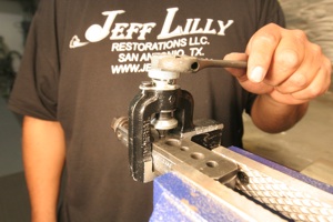
22. Hydraulic lines are all about flaring tubing to handle the high pressure. You will want a tool that comes with a variety of heads and can make double flares. |
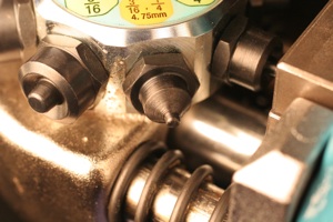 |
23. This picture shows the double flare head we will need. |
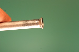 |
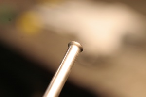
24. And here is a sample of the double flare it produces. |
 |
25. For stainless steel brake lines we need a special flair tool with a roller tip to assure that the flared surface does not get scratched. |
 |
26. Here is an sample of that flare. |
 |
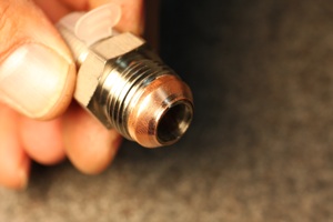
27. And here is the stainless steel tube with the a ferrule ready for installation. |
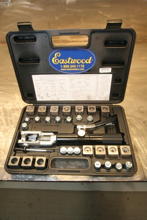 |
28. We use this Eastwood flare set (#11535). |
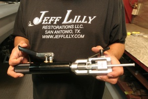 |
29. The tool is slim enough to go right up against the body panels in tight situations and it makes every type of flare you might need. |
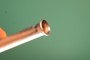 |
30. Here is a double flare we made with this tool. |
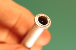 |
31. And here is a metric bubble flare we made. |
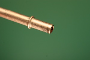 |
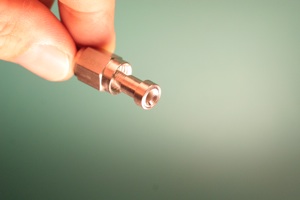
32. And here is a push connection flare we made for a vacuum hoses. |
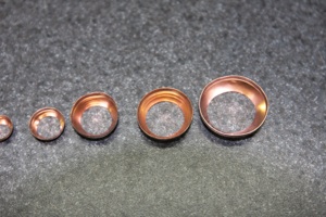 |
33. We use these copper gaskets between the fittings and flares on stainless steel brake lines so that we do not have to tighten the wrench as hard to get a good seal. |
 |
34. Here you can see how the copper gasket conforms to the fitting to make a good seal. |
 |
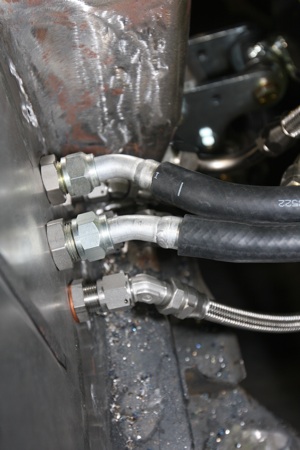
35. This picture shows you how we typically run various types of lines. Notice that they are all firmly attached to the body to prevent chaffing and in this case we will cover them with a trim panel to make them invisible. |
 |
36. And up inside the engine compartment, the bulkhead fittings were placed for the best hose route and appearance possible. |
Jeff Lilly Restorations
11125 F.M.1560 N
San Antonio, Texas
210-695-5151 - www.jefflilly.com
11125 F.M.1560 N
San Antonio, Texas
210-695-5151 - www.jefflilly.com